I have been wanting to upgrade the wimpy fluorescent lights in my house for a long time, but 2'x4' LED panels are expensive. I found a really good deal on some Cree panels so I bought enough to replace all the ones in my house. I wanted them to be smart compatible so I could use alexa to dim them and turn them off/on. Unfortunately These are commercial lights so they use 0-10v signals for dimming. I could not find any smart home compatible 0-10v dimmers so I set about building my own.
Circuit design
The way I wanted to divide up my lights meant that I needed 4 channels of 0-10v. I also wanted the ability to turn them on and off using physical buttons located near the light switches.
I found a decent library to use the ESP with alexa, so I used that as the brains of this. I got a quick sketch working that allowed me to control 4 channels. The bypass buttons will switch between Off, On, and whatever the last dimming setting was. Voice commands will override the state the button puts it in. Here is a video demonstrating it:
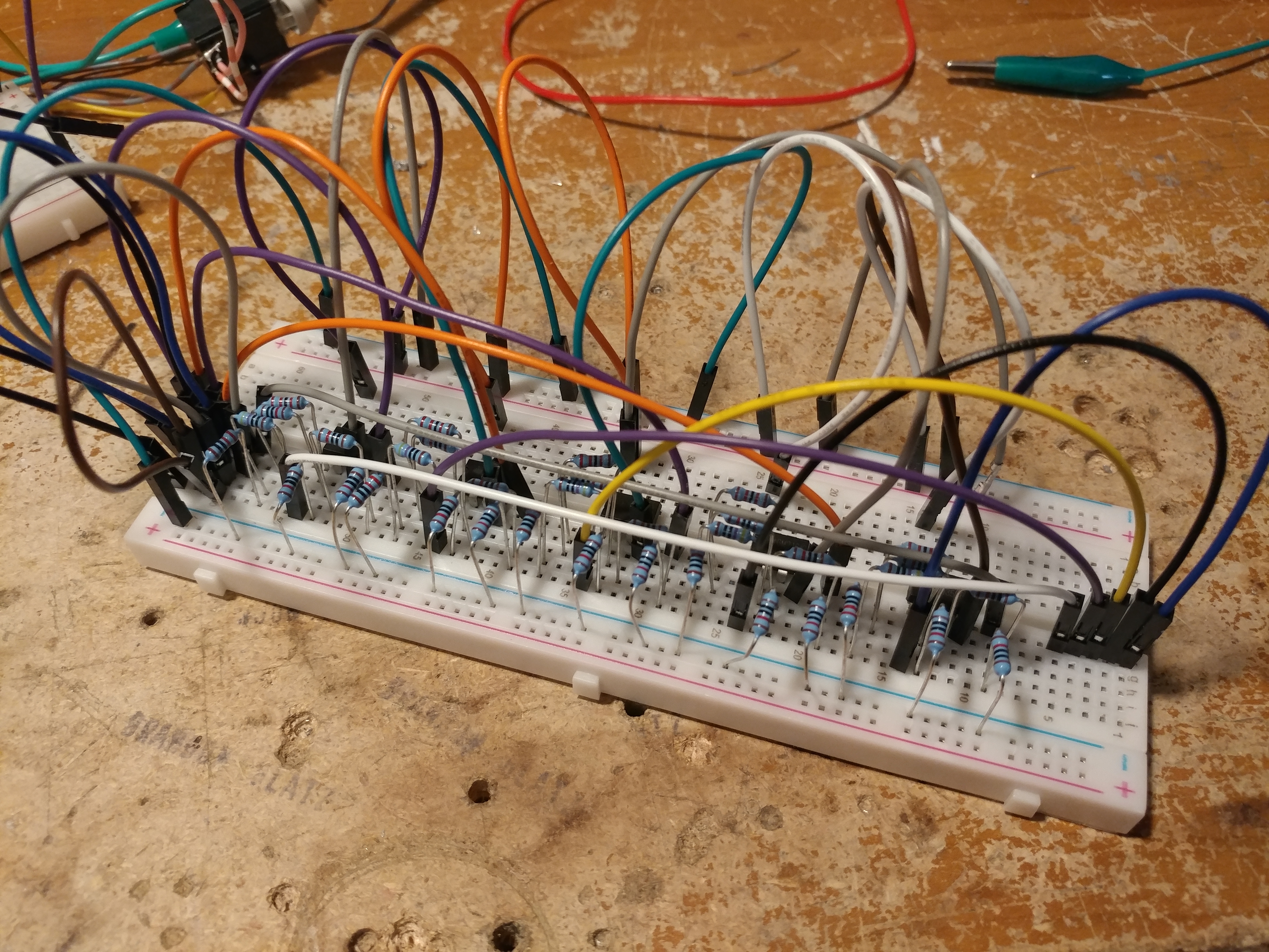
After getting this working, I did more prototyping to test a circuit using an opamp to generate 0-10v voltage signals. I made a bunch of the circuits to make sure there would be no problems chaining multiple together. The idea is to have a module at each light that takes in the pwm signal from the ESP and converts it into a voltage signal.
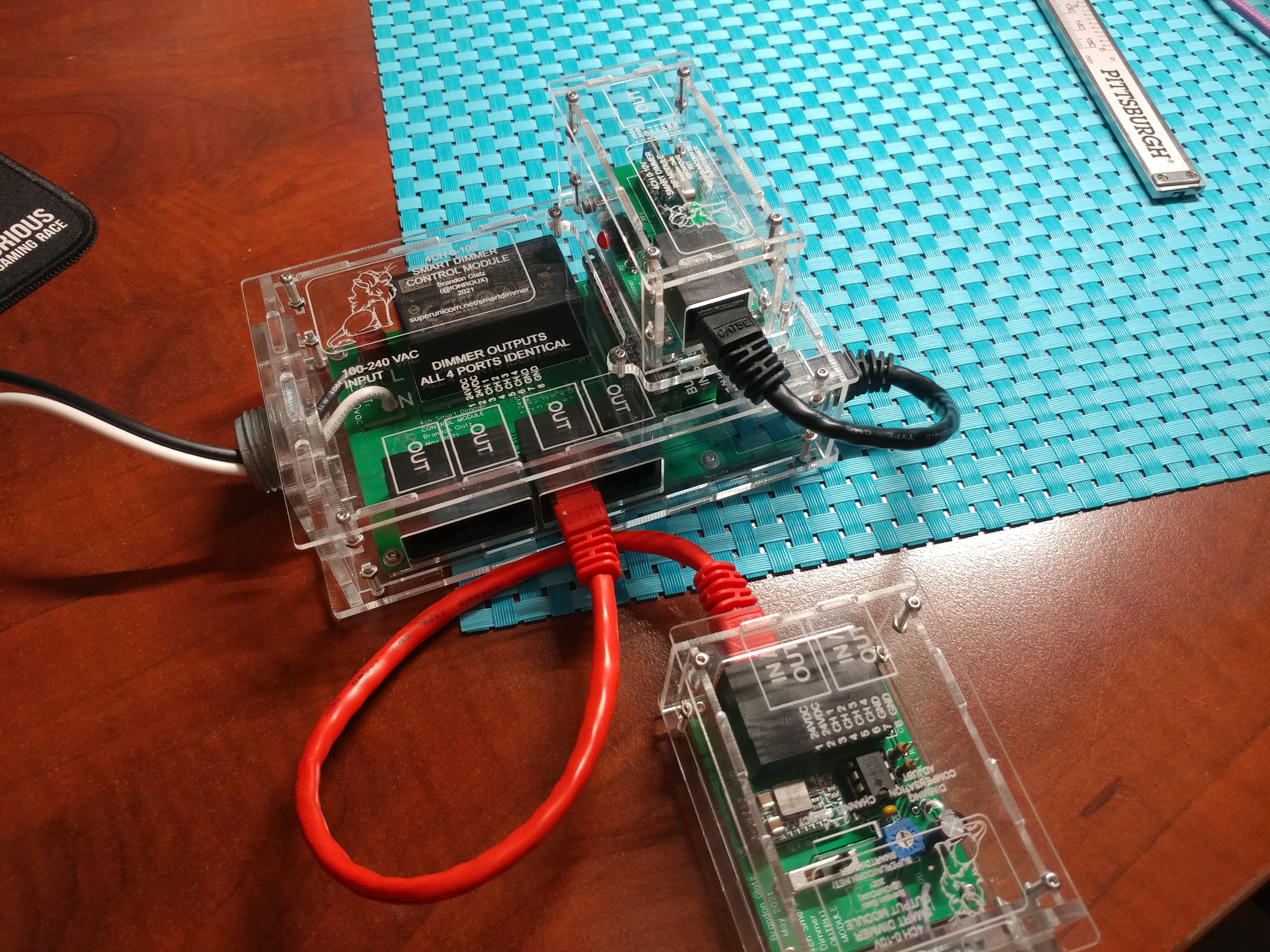
For ease of use, I wanted these to be connectable using normal ethernet cables.
I made a few light modules on protoboard to test with.
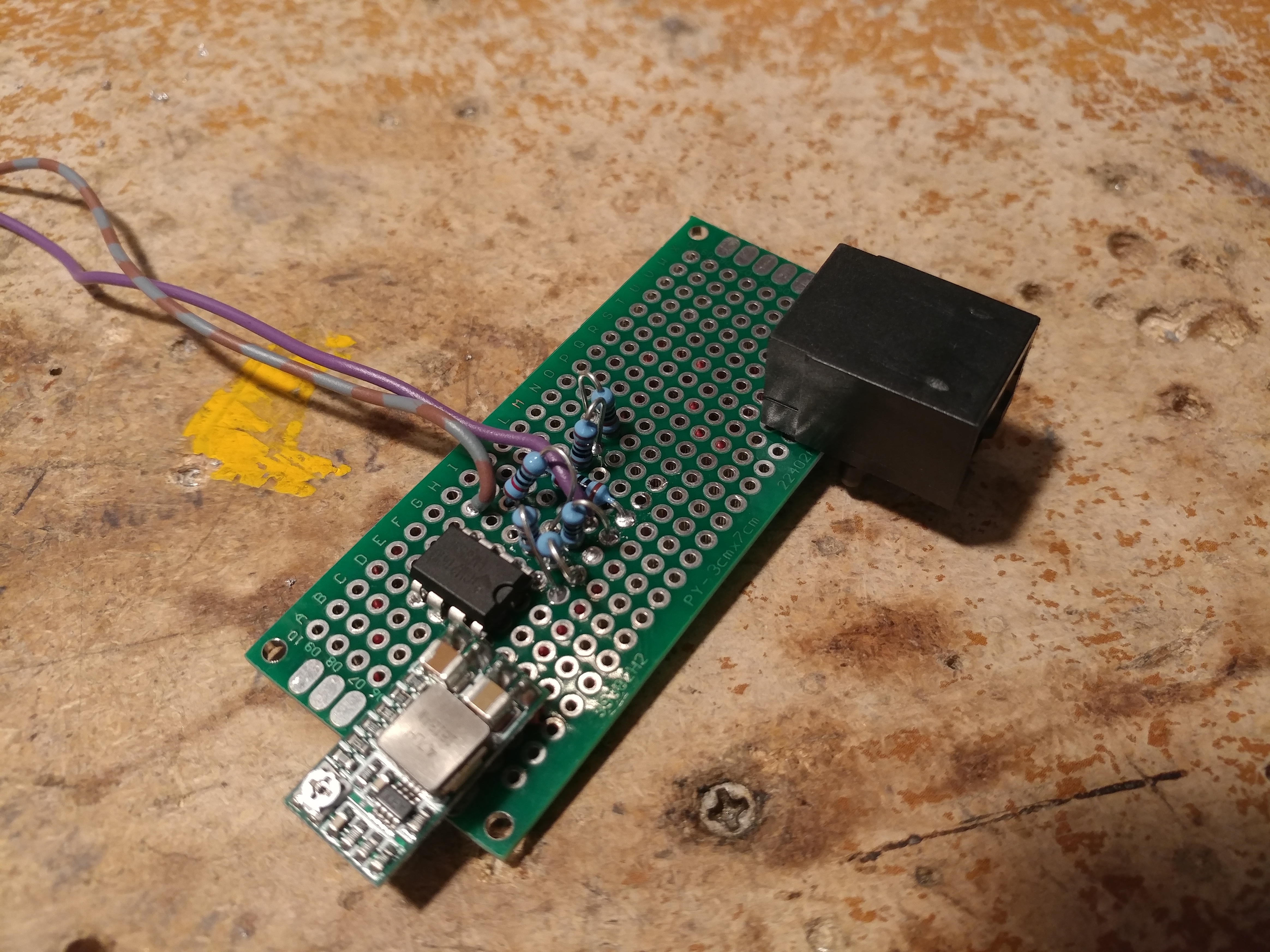
The ethernet cable carries 12V power and ground on 2 wires each using up 4 of the 8 wires in the ethernet cable. The other 4 wires are the pwm signals. Each lamp module has a small buck converter to generate the power for the opamp.

Once I verified the opamps would work for driving the lights, I added the remote buttons to the breadboard. I'm using common 433MHz buttons because you can get many styles and types on amazon or ebay.
One of the rooms has a 4 button remote so that I can control all 4 channels from one spot. Other rooms have a single button.

Once I had working prototypes, I started work on the final PCBs. Unfortunately I did not catch that the datasheet for the 12v power supply was the view as seen from the BOTTOM of the component. Oops, rev 2 here we go.
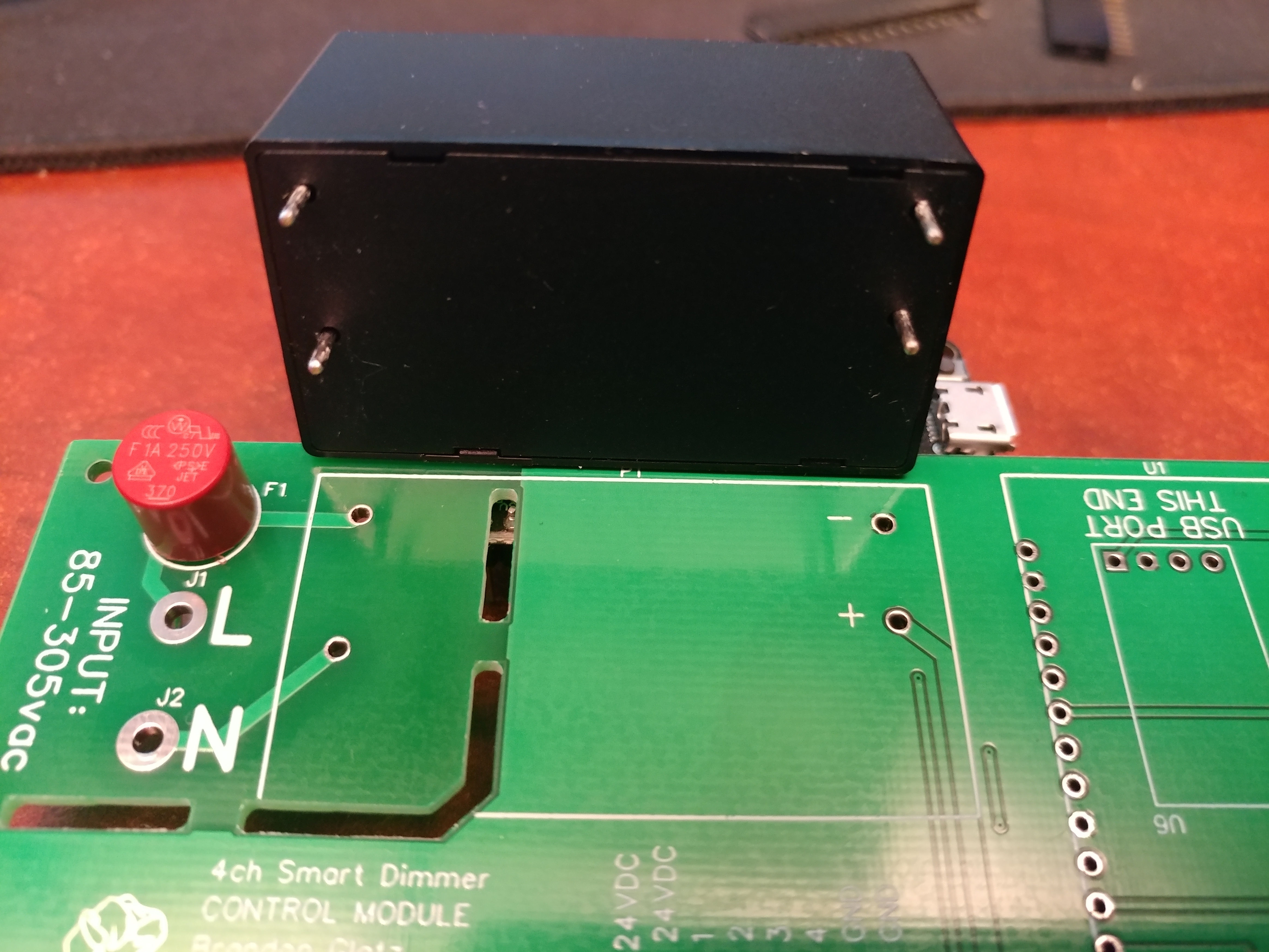
I ended up doing my testing by just soldering a 12v power supply to the board, that way I was not dealing with exposed 120vac.
Enclosure design
Now that I had working circuit boards, I needed a case for them and a way to mount them to the lights themselves. The lights have 1/2" knockouts on the electrical box, so I wanted to use that to mount the modules using chase nipples. I had my big laser cutter up and running so making these from lasercut acrylic was an obvious choice.
My first iteration just used friction to keep the top and bottom attached. This did not work well as different sheets of material had slightly different thicknesses so it would either be too snug or too loose. I did not want to risk these coming open so I had to change to a more secure design. You can see the chase nipple sticking out of the case as well .The plan is to have everything mount using these so the controller box can be mounted directly to a junction box.
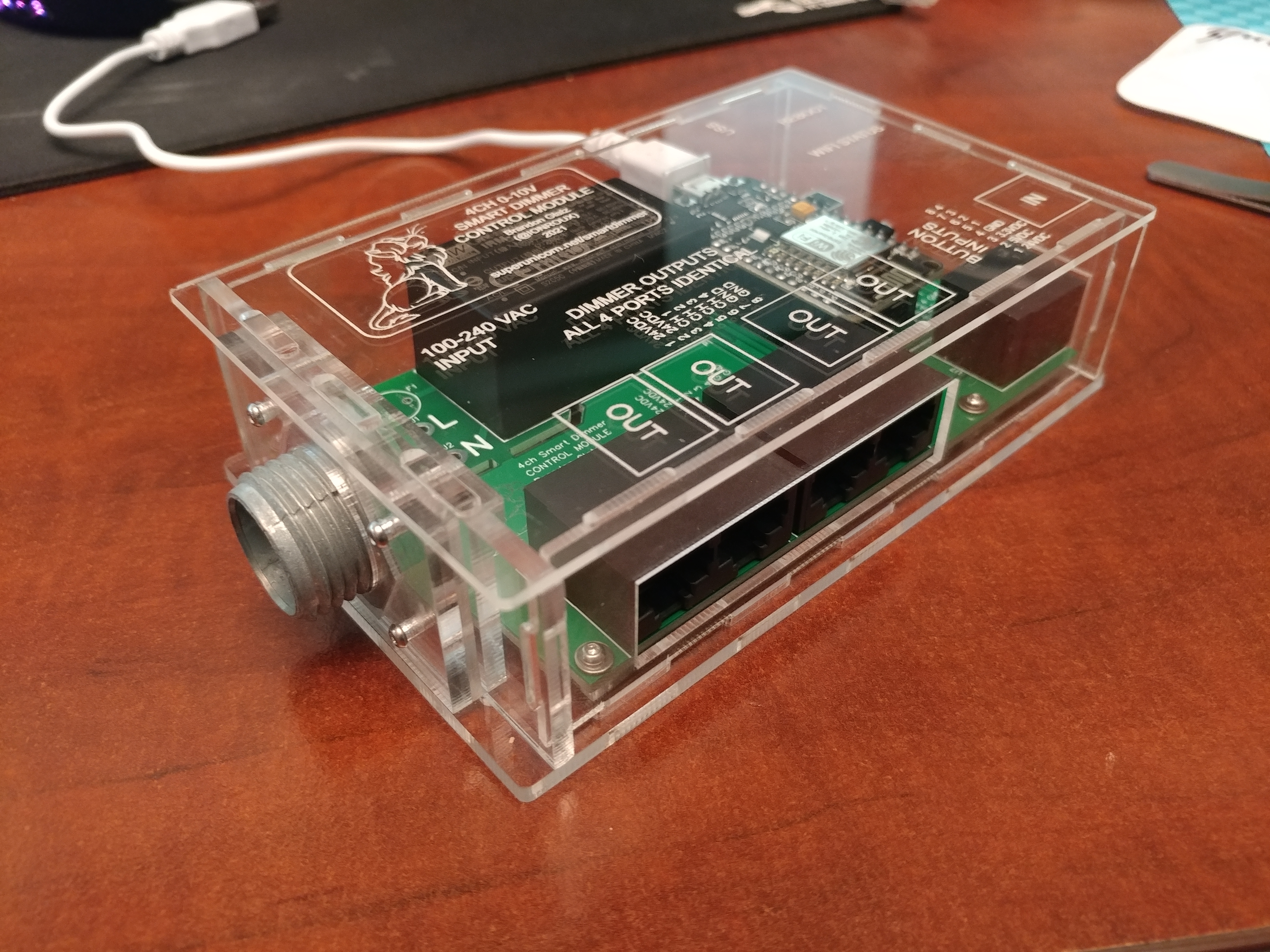
I oversized the slots and added some holes for screws to secure the top and bottom.
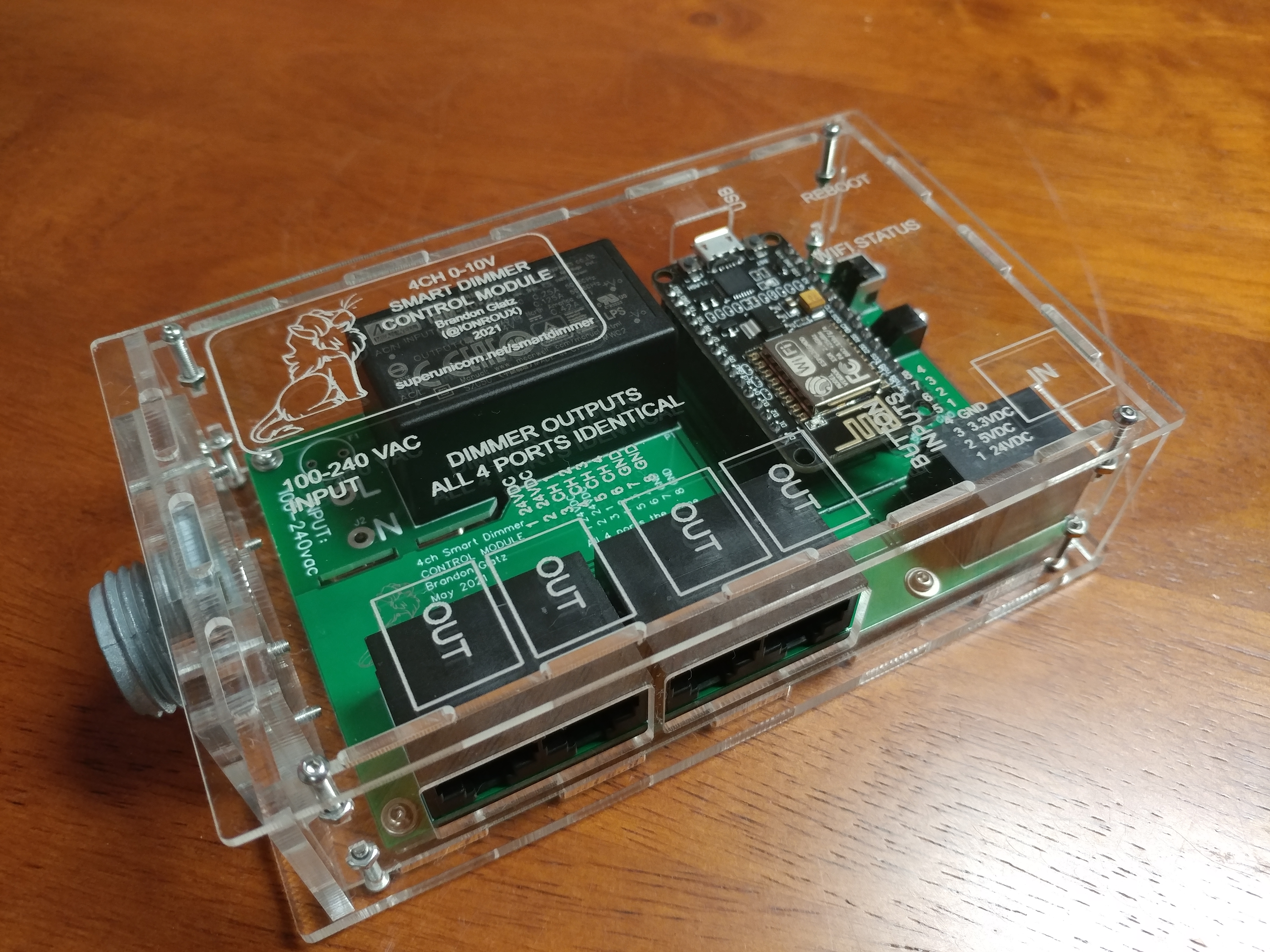
I spent a lot of time perfecting the case for the controller before moving on to the other ones so that if I made any changes I would not have to change it across multiple designs. I'm glad I did this as I ended up making a few changes. I made a lot of prototypes for this and used a lot of acrylic but it was my first real case design so that was to be expected. Once I was as satisfied as I could get with the controller case, I designed and cut the ones for the light modules and the remote receiver module.
I made the remote receiver a separate module so that it could be mounted separate from the control module in case there were signal problems. It can also piggyback on top of the control module if that is not needed.
I made a couple light modules to test everything, then started replicating.
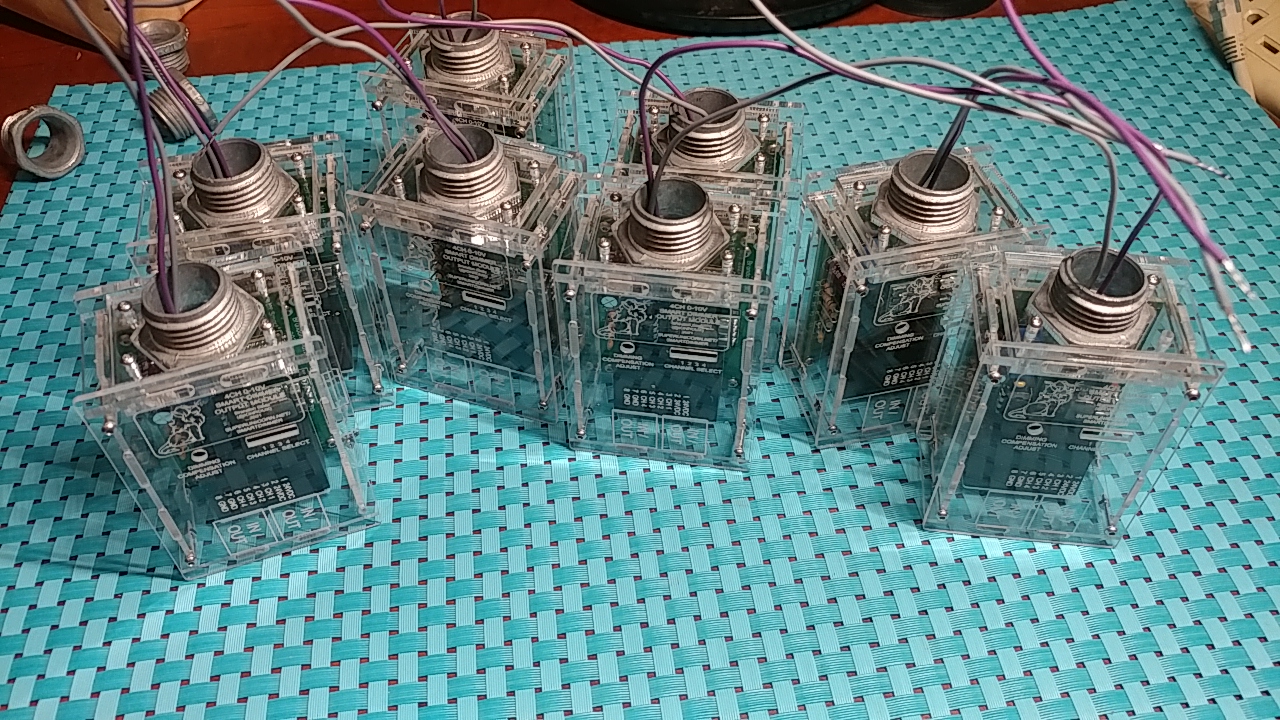
This is how they look on the back of the lights:
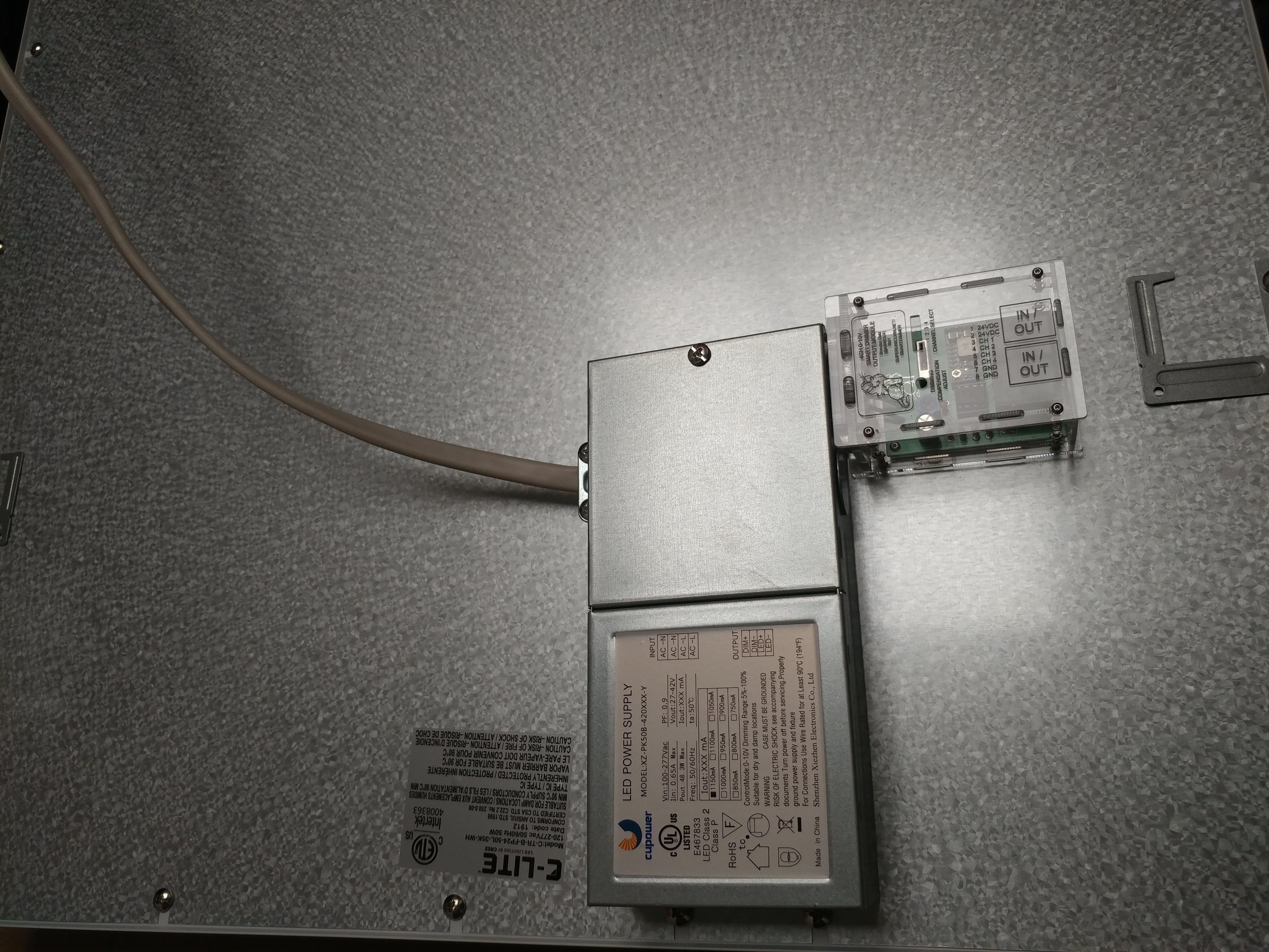
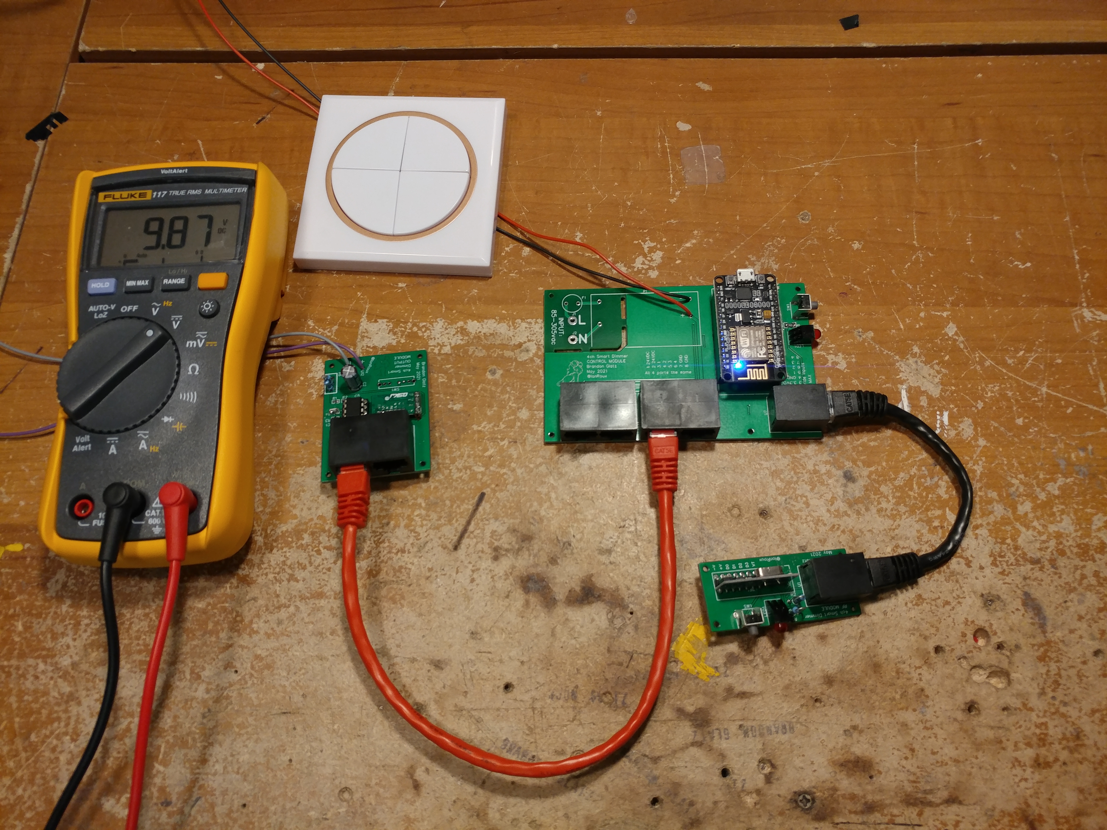
After having everything built I unboxed all 7 of the lights that would be controlled by these so I could do a full system test. Each light module has a potentiometer on it to fine tune the "off" point since it seems to vary from one light to another. Overtime the opamp or the light seems to drift so I have had to readjust them periodically when the light wont shut off.
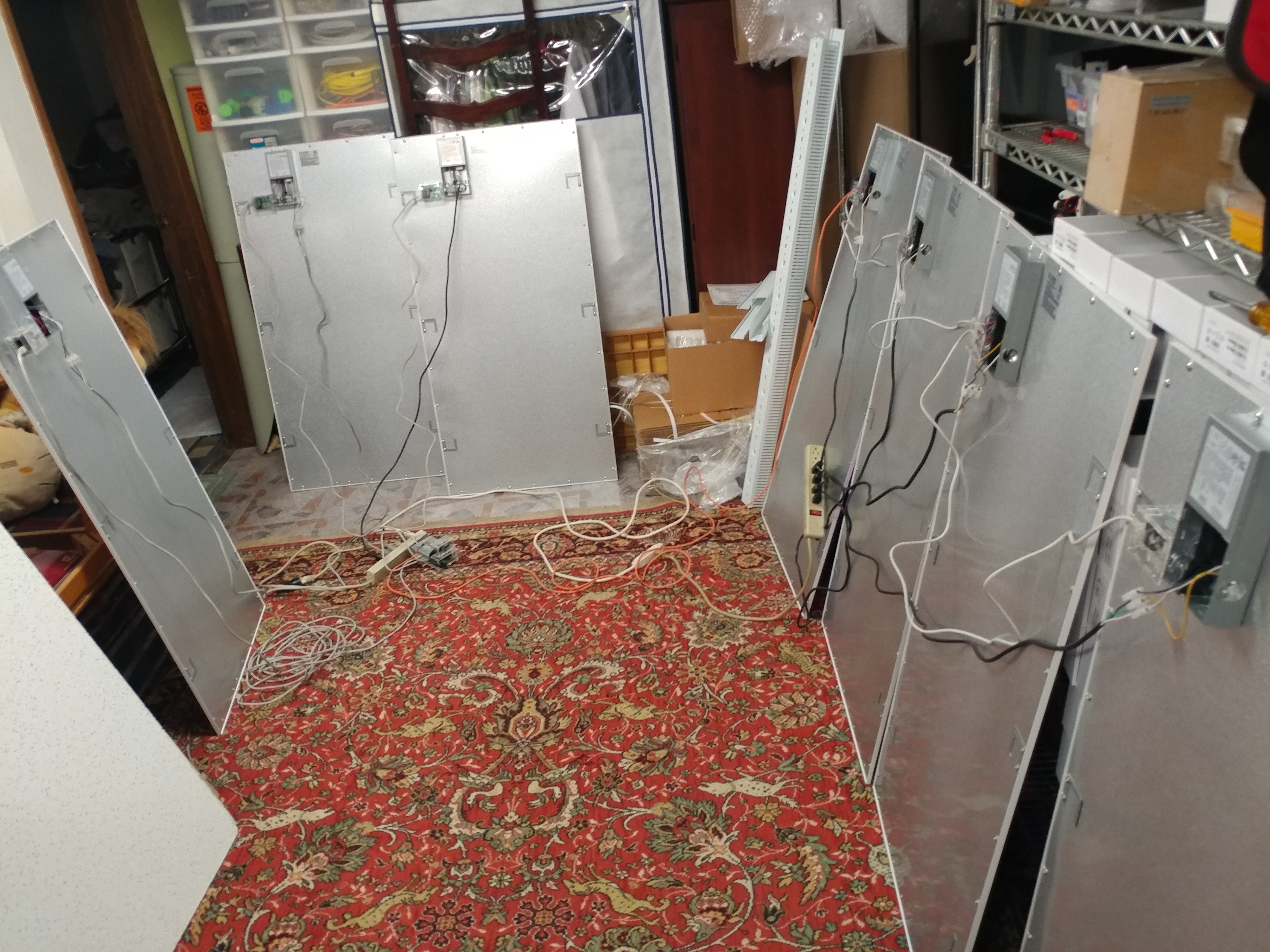
Here is a video of the test, channels 1 - 3 are each driving one light. Channel 4 is driving 4 lights. Each light module has 2 rj45 ports so they can be daisy changed. Also shown is the remote button override.
Final thoughts
It has been a little over a year since I finished getting all the lights installed and set up. I have made a few tweaks to the code to better handle the buttons but otherwise made no changes. I have had to adjust the off setpoint of a few lights because they seem to have drifted over the years. I'm not sure if it is the opamp wearing out or the light itself. I went a bit aggressive on the adjustment and have not had any issues. They can't get down to their dimmest possible brightness, but that is okay.
If I was going to do it again, I think I would try to make it fully wireless or at least addressable so that you aren't hard limited to 4 channels. Maybe some day I will revisit this project, but it is a lot of work to get to each light to replace each module so I doubt it.
